- Hits: 2533
LOX Mechanical Design

Overview:


For more specifications please download the FreeCad File:
Cooler Design:
The cooler is presented by a tunned refrigerator by adding seven cooling tubes inside it.

For more information check this report:
310821_ICPT_LOXPrototype(.docx)
- Calculation pressure of pipes
Equation: P = (2*S*T)/((O.D.-2*T)*SF)
Where:
P = Fluid Pressure (psi)
T = Pipe wall thickness (in)
O.D. = Pipe outside diameter (in)
Sf = Safety factor (General Calculations 1.5 – 10, Use 1 For Bursting Pressure)
S = Material strength (psi)
Ultimate Tensile strength or Yield strength can be used.
Ultimate should be used to determine the bursting pressure.
Yield can be used for estimating pressures at which permanent deformation begins.
1Mpa=144.55psi
In our case, We have 2 types of pipes: one made of aluminum (Al) and the other of copper (Cu). In the table below, information about these two types of pipes
|
Material |
Aluminum (Al) |
Copper (Cu) |
|
O.D. [in] |
0.3228 |
0.37874 |
|
T [in] |
0.037385 |
0.047244 |
|
S [psi] |
1450.3774 |
30457.9262 |
|
Sf min |
1.5 |
1.5 |
|
Sf max |
10 |
10 |
|
P [psi] (Sf min) |
655.84 |
15186.75 |
|
P [psi] (Sf max) |
4372.24 |
101244.97 |
|
P [bar] (Sf min) |
45.22 |
1047.09 |
|
P [bar] (Sf max) |
301.46 |
6980.60 |
Aluminum Pipe Equations Formulas Design Calculator [1]
[1] https://www.ajdesigner.com/phpaluminumpipe/pressure_rating_equation.php#ajscroll
Solving for pressure rating
Note:
Under most cases, S = 7500 pound/inch2 for aluminum


Our technical calculators can calculate weight, working pressures, copper tube thickness and wall diameter requirements.[2]
[2] https://lawtontubes.co.uk/technical-calculators/pressure-calculators/

- Prototype design
Initially, it was suggested to replace the main cycle (open oxygen cycle for liquefaction of oxygen) with a closed cryogenic cycle running on nitrogen gas for liquefaction of oxygen. This is due to the increased cost of the oil-free oxygen compressor, but it turned out later that nitrogen gas also needs an oil-free compressor, and for this reason we decided to return to the basic suggestion attached below.

In our prototype, we decided to dispense with the heat exchanger in order to avoid expensive materials and manufacturing costs. However, through the theorical study, it was found that we will face a problem in reaching the required liquefaction temperature, in addition to the compressor failure due the low gas temperature at the compressor inlet.
Therefore, the following was decided:

- Cooling component
In our system, the “Kelvinator” refrigerator has been adopted as a condenser for the compressor outlet. The second refrigeration cycle in the Kelvinator works with refrigerant R-503. This refrigeration cycle needs to be filled with refrigerant R-503. Due to its unavailability in the market, it was replaced with refrigerant R-508b, due to its compatibility with compressor oil.
13062022_ LOx prototype _ Mechanical design (docx)
A. Liquefaction of Oxygen _ Prototype
1) Overview _ Flow chart
LOX prototype flow chart by EDraw

2) Pipe sizing

3) Lox cycle calculation
Calculation of oxygen liquefaction cycle


4) Yield factor
Yield: Y = mf• / m• = h1-h2 / h1-hf
Where Point 1: before compressor (inlet)
Point 2: after compressor (outlet)
Y = (h1-h2)/(h1-hf)= (243.34-238.702)/(243.34-(-133.58)) = 0.012305 ≈ 1.231%
Y = mf• / m• ⇒ mf• = Y × m• = 0.012305 × 0.001243721Kg/s = 1.53039869×10⁻⁵ Kg/s
mf• = 1.53039869×10⁻⁵ Kg/s × 3600 = 0.0550944 Kg/hr
mass flow/density = mf•/ D ; where density D of liquid = 1141.8 Kg/m³
= 0.0550944Kg/hr/1141.8Kg/m³ = 4.8252192×10⁻⁵ m³/hr = 0.048252192 L/hr = 48.252192 mL/hr
B. Heat exchanger
1. Type of heat exchanger 
Types of heat exchanger used in cryogenic systems
We chose helical coil heat exchanger for many features
a. Shape of heat exchanger

Fig. 1 – Schema of a shell and helical tube heat exchanger [2]
[2] S. Bahrehmand, A. Abbassi, 2016. Heat transfer and performance analysis of nanofluid flow in helically coiled tube heat exchangers. Chemical engineering research and design 109 (2016), 628–637.
b. Characteristics of helical coil and shell
The copper pipe used has 9.62 mm outer diameter (O.D.) and 1.2 mm thickness. The coil pitch and the number of turns will be calculated in paragraph 2.c. The schema of the heat exchanger is shown in figure below. The shell inner diameter, outer diameter and height are 60 mm, 140 mm and 2.5 m, respectively.
c. Boundary condition
As can be seen in Fig. 1, hot fluid (Oxygen gas) at the specific temperature of -80 °C (193 K) with pressure 50 bar and mass flow rate inlet boundary condition enters the helical coil at the top and leaves at the bottom. Cold fluid (Oxygen gas) at a temperature of -183 °C (90 K) with 1 bar pressure and mass flow rate inlet boundary condition enters the shell at the bottom and leaves at the top.
Equal values of mass flow rate were specified for shell-side and coil-side fluids.
d. Performance analysis of the heat exchanger
Heat transfer enhancement was experimentally investigated by by Jamshidi et al.(2013) [3]. It was observed that the increase in coil diameter, coil pitch and mass flow rate in shell and tube can enhance the heat transfer rate.
It is also seen that the increase in tube diameter and coil diameter enhances the effectiveness because the heat transfer area increases.

Fig. 2: Variations of performance index vs. mass flow rate based on various parameters [3].
Furthermore, it can be observed from Fig. 2 that with the increase in tube diameter the performance index enhances remarkably. The reason can be attributed to the significant decrease in pressure drop, the increase in heat transfer area and enhanced secondary flow.
The heat transfer rate enhances with coil diameter due to increased heat transfer area and the pressure drop increases with coil diameter because of increased length of the tube.
The effect of coil diameter on pressure drop is more intensive than that of heat transfer rate; consequently, the performance index decreases with an increase in the coil diameter.
For all cases, the optimum value of mass flow rate corresponding to maximum performance index is found to be 0.1 kg/s.
[3] Jamshidi, N., Farhadi, M., Ganji, D.D., Sedighi, K., 2013. Experimental analysis of heat transfer enhancement in shell and helical tube heat exchangers. Appl. Thermal Eng. 51,644–652.
e. Advantage of Helical Coil Heat Exchanger
Helical coil heat exchanger has many benefits that make it a good choice:
- Highly efficient use of space, especially when it’s limited and not enough straight pipe can be laid.
- Under conditions of low flowrates, such that that the typical shell-and-tube exchangers have low heat-transfer coefficients and becoming uneconomical.
- When there is low pressure in one of the fluids.
- When one of the fluids has components in multiple phases (solids, liquids, and gases), which tends to create mechanical problems during operations, such as plugging of small-diameter tubes. Cleaning of helical coils for these multiple-phase fluids can prove to be more difficult than its shell and tube counterpart; however, the helical coil unit would require cleaning less often.
2. What need to consider when design Helical Coil Heat Exchanger
a. Materials
When designing the helical coil heat exchanger, the first thing you need to consider is what material you should use. Copper tube and Stainless-Steel tube are two most common choices. Copper tube have relatively higher heat exchange rate, because copper tube is softer. Stainless steel tube doesn't react with water, which make it last longer, especially when one of the heats transferring fluid is water.
In our case, we will use the copper tube, because stainless steel tubes are not easily available in Lebanon.
b. Design of heat exchanger

c. HX FreeCAD design
Helical coil heat exchanger freeCAD design (v0.17)


Sizing of Helical coil heat exchanger (pptx)
d. Heat exchanger calculation
a) Thermal calculation
1) Average temperature LMTD △tm =?
We have:
Warm side: Temperature In = 195 K
Temperature Out = 155 K
Cold side: Temperature In = 90 K
Temperature Out = 153 K
LMTD = (△ T1 - △T2) / ln (△T1/△T2)
For counter current:
△ T1 = Twarm in – Tcold out = 195 – 153 = 42
△ T2 = Twarm out – Tcold in = 155 – 90 = 65
⇒ LMTD = 52.67
2) Heat flux Q=?
We estimate G = 0.1 Kg/sec with
Qhot = G.C.(t2f – t2i)
Where:
Q - quantity of heat transferred or received by the heat transfer medium [W],
G - hot and cold heat transfer medium flow rates [kg/sec],
C - heat capacity of hot and cold heat transfer media at (50 bar, 195 K) [kJ/Kg.deg], C= 1.4 kJ/Kg.K
t2f - final temperature of cold heat transfer media [°C or K],
t2i - initial temperature of cold heat transfer media [°C or K].
⇒ Q = 0.1*1.4*(193-155) = 5.32 kW
b) Design calculation
1) Heat exchange surface A=?
The approximate heat exchange surface is calculated as follows:
Q = U × A × LMTD
Where:
A - Heat exchange surface [m2]
U: the overall heat transfer coefficient [W/m2.K], by estimation based on tables below U = 150 W/m2.K;

⇒ A = Q / (U × LMTD)= 5320 / (150 × 52.67) = 0.6733 m2
⇒ A ≈ 0.68 m2
2) Length of tube L=?
During the design calculation of coil heat exchangers, the total length of the coil as well as the number of turns and sections are determined.
L = A/π dp
With :
L - total length of the coil [m],
A = 0.68 m2,
dp – design diameter of the coil tube [m]; dp = 9.5 mm = 0.0095 m
⇒ L = 0.68/(π × 0.0095) = 22.8 m
3) Number of turns n=?
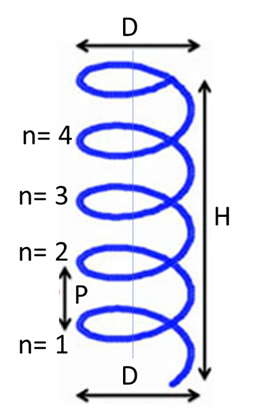
n – Number of turns
P – Pitch
H – Height
D – Diameter
C – Circumference of spiral
We have L = 22.8 m
We estimate D = 10 cm & P = 3 cm
Circumference : C = π × D
D = 12 cm = 0.12 m ↠ C = 0.31416 ↠ C2 = 0.0987 m2
P = 3 cm = 0.03 m ↠ P2 = 0.0009 m2
Length of helix: L = n√(C2 + P2)
⇒ n = L / √(C2 + P2) = 22.8 / √((0.31416)2 +(0.03)2) = 72.243 turns
⇒ n ≈ 72.3 turns
With n = H/P ⇒ H = n × P = 72.3 × 0.03 = 2.169 m
⇒ H ≈ 2.2 m
3. Measurement summary of the Helical coil heat exchanger

4. List of HX prices

5. Cooling pipes (Inside Kelvinator refrigerator)
a. Average temperature LMTD △tm =?
We have:
Warm side: Temperature In = 263 K
Temperature Out = 195 K
Cold side: Temperature In = 193 K
Temperature Out = 193 K
LMTD = (△ T1 – △T2) / ln (△T1/△T2) = 19.13
b. Heat flux Q=?
Qhot = G.C.(t2i – t2f) where G=0.00094854 Kg/s
= 0.00094854kg/s×1.0341KJ/Kg.K×(263-195)K
= 0.667 KW ≈ 667 W
C. Length of tube L=?
Q = U × A × LMTD
⇒ A = Q/(U×LMTD)= 667/(50×19.13) = 0.6974 m2 ≈ 0.7 m2
L = A/ π dp where dp = 7.9 mm = 0.0079 m
⇒ L = 0.7/(π×0.0079)= 28.205 m
Corrective length:
Lc = L ×safety factor = 28.205 × 1.05 = 29.615 m ≈ 30 m

https://manibhadrafittings.com/copper-pipe-weight-dimensions-chart-in-mm-kg/
C. Compressor
1) Specifications of compressor

2) Calculation of rated capacity
Mass flow / Density = volumetric flow
Capacity = 3.6*volumetric flow
[Kg/s] ÷ [Kg/m³] = [Kg/s] × [m³/Kg] = [m³/s] = 1000 [L/s]
[m³/s] = 3.6 [m³/h]
D. Expansion valve
In this LOx prototype, we need a cryogenic expansion valve, that has the following features:

A cryogenic expansion valve was not found operating on oxygen gas. therefore, this valve will be replaced by an open-close solenoid valve coupled to a pressure sensor. The solenoid valve, at the request of control, opens when the pressure sensor senses a pressure of 50 bar and closes at 45 bar.
1) Pressure sensor
2) Solenoid valve
We need a cryogenic solenoid valve that have some specifications:
- Pipe size: 3/8”
- Nominal pressure: 50 bar
- Temperature: 90 K to 320 K

3/8” size not available. 1/4” or 1/8” is accepted as an alternative pipe size, we can choose between 4 valves found in the S9610 series. Available pressure value up to 100 bar.
Solenoid valve catalogue (pdf)


The valve is useful for Cryogenic Fluid, Liquid Oxygen, Hydrogen, Helium, Carbon Dioxide, Nitrogen.
https://smstork.com/en/user-manuals

- Causes of leakage of low temperature solenoid operated hydraulic control valve
There are two reasons for the leakage of low temperature solenoid operated hydraulic control valve, firstly the main reasons are the seal deformation in the low temperature state. When the temperature of the medium is decreased, the volume change is caused by the phase change of the material, and the sealing surface with high grinding precision is produced to cause warpage, leading to the bad sealing. Two is the external leakage. It is mainly due to the flange connection between low temperature solenoid valve and pipe, due to the connection pad, connecting bolts, and the connection between the material at low temperature shrinkage caused by the relaxation of the gap and lead to leakage. Therefore, the connection mode between the valve body and the pipeline can be changed to the welding structure, then the low temperature leakage can be avoided. Another is the stem and packing leakage. These are the main reasons for the leakage of low temperature solenoid operated hydraulic control valve.
3) Two phase separators
Separation of the liquid and gas starts when the fluid meets the baffle. At that point, the gas and liquid start to go in different directions. The liquid drops where it is collected at the bottom of the vessel, and the gas rises to the top of the vessel. The gas that is still held in the liquid is in a section called the gas/liquid emulsion, which is in an area at the top of the liquid. In time, the gas is released from the emulsion and rises to the top of the vessel where the rest of the gas resides. Depending on the process, this may contain a mist eliminator or demister. The gas leaves from the top of the vessel, and the liquid leaves from the bottom of the vessel, heading to the next process.

In one hour :
Inlet compressor : 3.229 m³/hr @ 278K (≈ +5°C)
3.402 m³/hr @ 293K (≈ +20°C)
3.634 m³/hr @ 313K (≈ +40°C)
Inlet of solenoid valve: V4• =0.6 L/min =0.036 m³/hr @ 155K, 50 bar
P4.V4/T4=P5.V5/T5 ⇒ V5 = P4.V4.T5/T4.P5 = (50×0.036×90.062)/(155×1) = 1.04588 m³/hr = VT•
1.04588 m³ → 100%
? ← 0.169%
⇒ Vf• = VL• = 0.00177 m³/hr = 0.5 mL/s @90.062K, 1 bar
Vg•= 1.04411 m³/hr = 0.0123 L/s @90.062K, 1 bar
Total volume of separator:
In 1 hour: VT= 1.04588 m³
a) Sizing of separator
- Specifications:
Horizontal/vertical: Vertical
Material: stainless steel
Pressure: 5MPa
Thickness: 8mm

- Sizing details depend on volume

N.B.: Changing the volume of the separator does not affect the size of the pipes (inlet/outlet). In other words, the pipe size will remain constant, and it is not related to the volume of the separator.
- Design of separator
Separator design_FreeCAD (v0.17)


E. Insulation material of LOX prototype
- Cryogenic insulation material

⁺ https://www.grainger.com/category/plumbing/insulation/pipe-insulation?attrs=Fits+Tube+Size%7C3%2F8+in&filters=attrs

⁺ https://www.grainger.com/category/plumbing/insulation/pipe-insulation?attrs=Fits+Tube+Size%7C1%2F4+in~~Insulation+Temp.+Range%7C-297++Degrees+F+to+300++Degrees+F&filters=attrs&gwwRemoveElement=true

⁺ https://www.techapps.com/hs-fs/hub/165629/file-18313511-pdf/documents/technical_paper_cost-efficient_storage_of_cryogens.pdf
F. Operating system
1) Preparing the system for operation
- Ensure that all components of the system are connected
- Ensure that the system is free of leaks
- Ensure that the insulators are placed correctly and in the appropriate places
- Verify that electrical connections are correct
- Make sure the valves are working
- Make sure the oxygen tank is full
- Fill the system tubes with oxygen
2) Operation system
The first step to operate the system begins with operating the compressor, where the oxygen gas is pumped from the tank at ambient temperature (2 bar) to the pipes by the compressor. Oxygen gas passes through the tubes at a pressure of 50 bar. It is inserted into the Kelvinator refrigerator, which plays the role of a cooler, to cool the oxygen passing through the pipes from +10 °C to -78 °C (283 K to 195 K). The compressed oxygen exits from the cooler and enters the heat exchanger. Compressed oxygen exits from the heat exchanger at -118 °C (155 K) and passes into the solenoid valve, which opens at a pressure of 50 bar and closes at 45 bar. When the pressurized oxygen passes through the solenoid valve and the separator, the oxygen expands and its pressure drops from 50 bar to 1 bar. The fluid temperature also drops from -118 °C to -183 °C (from 155 K to 90 K). At a temperature of -183 °C (90 K, 1 bar), part of the fluid turns into liquid oxygen (1.23%) and collects at the base of the separator, while the other part remains in its gaseous state (98.77%), with a temperature close to the liquefaction temperature (-183 °C (90 K)), where it returns to the exchanger to play the role of a cooling medium for compressed oxygen gas passing through a coil. Oxygen gas comes out of the heat exchanger at a temperature of -120 °C (153 K, 1 bar) to reach the mixer, where the cold gas coming out of the heat exchanger is mixed with a certain amount of oxygen gas in the tank. This quantity is equivalent to the amount of liquid produced, taking into account the difference in pressure and temperature, and therefore the volume. The oxygen gas is then transferred to the heater, where it is heated to -10 °C (263 K) to re-enter the compressor again.
Notes:
1- The required temperatures will not be obtained from the first pass (cycle #1), but this requires several cycles in order to cool the gas itself and the system.
2- The high pressure and cryogenic temperature may cause fractures (cracks) in the pipes and this may lead to an explosion, so the system must be tested with an upward pressure to reach a high pressure (5bar, 10 bar, 15 bar, …, up to 50 bar).
3- The safety valve (pressure reducing valve) must be placed at the highest point of the pressure tube in the system, to leak excess pressure in the system, especially after stopping the system from working.
Related Sites/Items:
|
System Specification |
|
|
Mechanical Design |
|
|
Process Control System Spec./Design |
|
|
Mechanical Realization |
|
|
Process Control System Realization (PLC+GUI) |
|
|
System Test Specification |
|
|
System Testing |