- Hits: 4036
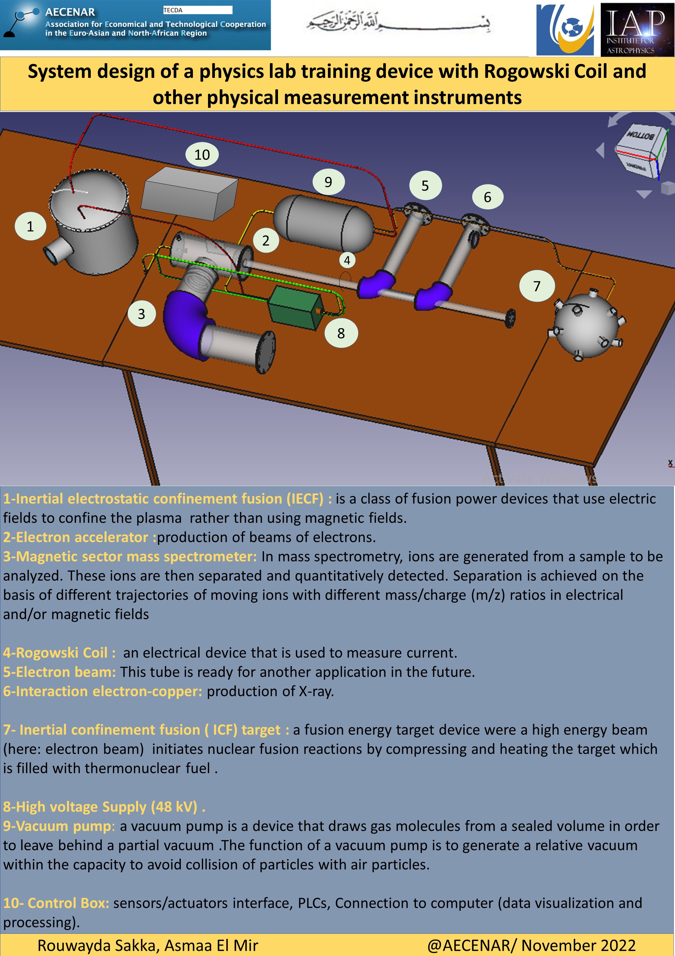
IAP Physics Lab
IAP-PhysicsLab Design and X-Ray
Master Thesis Of Rouwayda (docx)
Memoire De Master Rouwayda (docx)
Mass Spectrometer
Master Thesis Of Asmaa (docx)
Memoire De Master Asmaa (docx)
Master Thesis of Asmaa, Last update: 15.11.23, Defended in Jan 24 (docx)
IECF
IAP Report 2022(docx)
IAP Report 2022 (PDF)
Factors affecting X-rays spectrum :
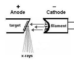
To obtain X-rays, it is necessary to have a filament which is called a cathode, in addition to an anode. This anode must be tilted at an angle. This angle is called the anode angle.
And the electrons will come out of the filament and hit the anode. They begin to emit X-rays after touching the anode.
Thus, the X-rays come out due to the electrons exiting the filament and their interaction with the anode.
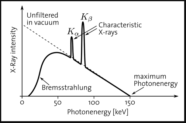
And the X-rays we get are of two types: characteristics radiation and Bremsstrahlung radiation.
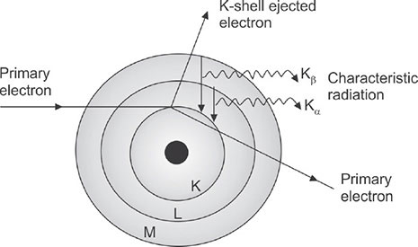
Characteristics radiation: And that due to the interaction of the electrons leaving the cathode with the electron shell, that is ,with the electrons present in the atomic energy levels of the anode atom.
I have an atom composed of nucleus and shells; An electron comes out of the cathode and hits an electron in the K shell.
Then it removes that electron, the electron in the L shell begins to descend into the K shell to fill the gap in the K shell.
As a result of this transition, we get energy. This energy is called X Ray Characteristics.
So the electron will fall from the L shell to the K shell. And we get the characteristics X radiation, this is called Characteristics K-Alpha radiation.
And if the electron falls from the M shell to the K shell, then we call it Characteristics K-Betta radiation.
So what we will get as a result of the energy difference between the energy in the M shell and the energy in the K shell is what is called the X-ray energy.
We will assume that the binding energy in the K shell is 70ev, and the L shell is 11ev, and the M shell is 2ev.
If an electron falls from the L shell to the K shell, the difference in energy is 70-11= 59 Kev. So the x-rays that we get are going to have an energy of 59 Kev.
If an electron falls from the M shell to fill the void in the K shell, then the energy is equal to 68 Kev. So this is the energy of the x-rays coming out as a result of the interaction between the electron coming from the cathode and the K shell.
Note: the energy of the electron falling from the cathode to the anode must be greater than the energy of the K shell, in order to obtain the Characteristics X-ray. If it is smaller than that, we will lose our ability to eject an electron from the K shell.
For example, if my target material is tungsten, the binding energy of K shell for that target is 70 Kev. So the volts that i will use that will give kinetic energy(i.e.the kinetic energy of the electron in order to move from the cathode to the anode, in order to obtain characteristics X-rays) the volts apply must be greater than 70 Kev.
Bremsstrahlung radiation: I have a fast moving electron that interacts with the coulomb field around the nucleus.
The nucleus has a positive charge, it will attract the electron falling on it, which passes next to it, and change its path(deflection);
as a result of this deflection, the electron loses kinetic energy, and this energy that it loses appears in the form of an X-ray.
This is the Bremsstrahlung X-ray.
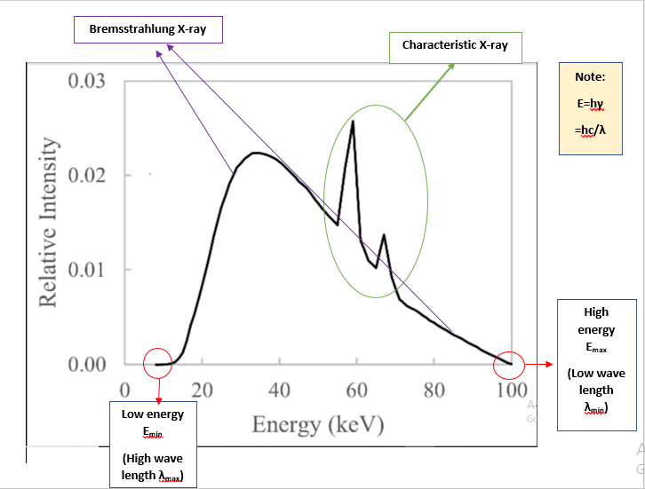
Spectrum of X-ray:
Are all rays that come out, will come out with the same energy? Rather, it will produce different cards, depending on the electron and its interaction with whom!
When the electron falls on the target, will it interact with the surface atom, with the atoms on the surface or with the deeplayers? Of course, it will not only interact with the atom.
It can interact with the atoms on the surface, losing part of its energy, and then entering the next atom.
So there is difference interactions with the deeplayers that are present with the anode. It can interact with the atoms on the surface and then interact with other atoms, or it can interact with the interior atoms immediately.
So the amount of energy lost will be different depending on the location in which the electron will interact exactly, on the surface of the anode or on the deep layers, it is normal to obtain a different amount of X-ray energy.
So i get a spectrum like this:
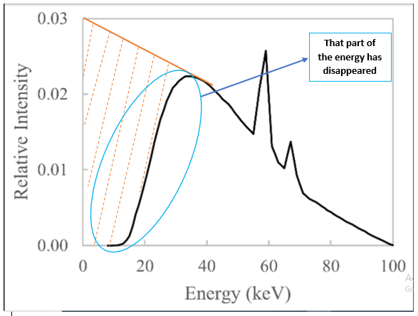
Filtration:
In fact, the X-ray image that will appear to me is as follows:
We will notice that some of the energy will disappear, and the reason for that is that i have done filtration, that is, i used a material that has a certain thickness.
This material could be aluminum, copper...So this material has enough thickness to remove the low energies.
So when we put filtration, we will get this spectrum. So we remove the low energies in order to work only on the high energies; Which makes the spectrum that i will get more homogeneous (and this is good to use).
So the filtration had on effect on the shape of the spectrum.
Most of the outgoing photons carry an energy of one third of the maximum energy; In our case around 30 to 40 Kv.Fewer lower energy photons.
Increased:
* Average energy of photons.
Decreased:
* Total number of photons.
When we increase the filtration, we increase the low energies of photons. So the average of energy will increase.
On the other hand, the number of spectrum will decrease and the total number of photons will decrease.
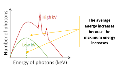
The effect of increasing the tube potential volts(Kv):
If i use high Kv, it is normal for my maximum energy to increase, as well as the probability of interactions between electrons and the target of the anode, which leads to an increase in intensity.
Increased:
* Quantity of X-ray photons.
* Average energy.
* Maximum energy.
If Kv great enough, characteristic energy produced.
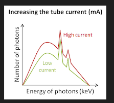
The effect of increasing the tube current (mA):
Increasing the mA will increase the X ray photons because we have increased the number of electrons. This would increase the number of interactions and thus the number of photons, and thus the intensity or the curve would become higher.
But the average energy will not change because it is related to the value of the Kv. As long as Kv is constant, average energy and minimum and maximum energy will not change.
Did the characteristic energy change? No.
Did the average energy change? No.
Only the intensity of spectrum has changed.
Increased quantity of X-ray photons:
No change in:
* Characteristic energy.
* Average energy.
* Minimum energy.
* Maximum energy.
[ Note: The minimum changes due to filtration only].
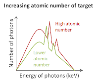
Increasing atomic number of target:
If we change the material we use as the anode and use another material that has a larger atomic number, this will affect the shape of the spectrum.
It will increase the X ray photons, that is, the number of photons that the more the Z number increases, the more the number of atome increases. Thus the probability of interactions became higher.
In this case the quantity of X ray photons will increase. As for the minimum & maximum, they will not change because one of them depends only on the filtration, and the second depends only on the Kv.
The spectrum itself is the one that has become higher. The amount of increase in the spectrum is the result of the change in the atomic number, which would also become higher in the characteristic energy, i.e. the pic previously was somewhat low, and after increasing the atomic number it will become more because the increase in The atomic number increases the bonding energy of the electrons in the K shell.
The energy difference between the levels that we will obtain will have a higher value.
In this case, the value of the characteristic X ray will increase. The average energy will not change because it is related to Kv.
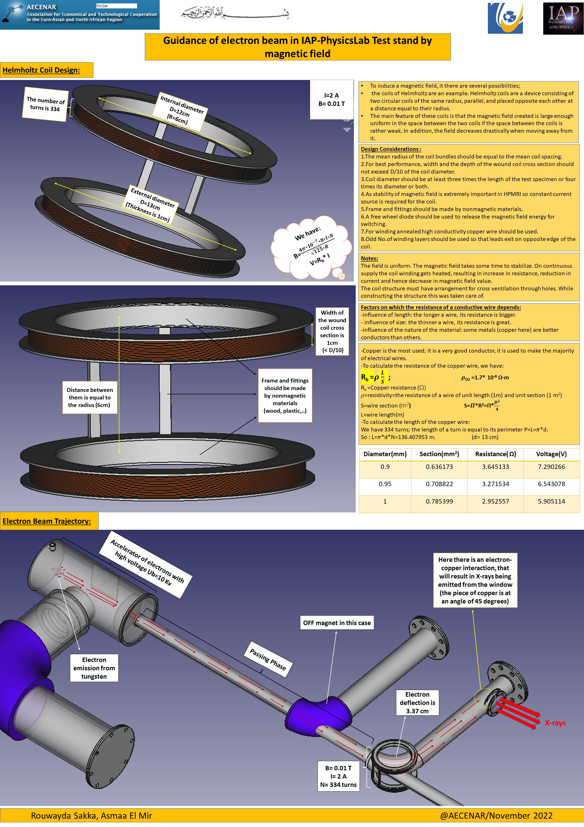
Helmholtz coil:
Helmholtz coils are a device consisting of two circular coils of the same radius, parallel, and placed opposite each other at a distance equal to their radius. By flowing electric current through these coils, a magnetic field is created in their vicinity, which has the distinction of being relatively uniform at the center of the device in a smaller volume than the coils themselves.
This type of coils are often used in physics to create relatively weak quasi-uniform magnetic fields with little material. For example, it can be used to eliminate the earth's magnetic field so that it does not interfere with an experiment.
Helmholtz coils have the advantage of having a uniform field distribution in a very accessible area of space between the two coils.
To obtain stronger magnetic fields, it is necessary to use more expensive soft ferromagnetic material such as an electromagnet. However, the absence of hysteresis in coils without a ferromagnetic core makes them preferred over electromagnets in cases where the field must be precisely calibrated around zero and in high frequency studies.
The field of each coil is inhomogeneous. By superimposing the two fields, a zone is obtained between the two coils with a practically homogeneous magnetic field.
The magnetic field intensity is directly proportional to current and the number of turns in the coil and it is inversely proportional to the distance between the coils.

For the magnetic field in horizontal direction and a coil with only one winding applies:(this equation is indicated by Biot-Savart law)

The magnetic field at center of two Helmholtz Coils is the superposition of two circular currents.For symmetry reasons it becomes:

For N turns :

Design Considerations:
1. The mean radius of the coil bundles should be equal to the mean coil spacing.
2. For best performance, width and the depth of the wound coil cross section should not exceed D/10 of the coil diameter.
3. Coil diameter should be at least three times the length of the test specimen or four times its diameter or both.
4. As stability of magnetic field is extremely important in HPMRI so constant current source is required for the coil.
5. Frame and fittings should be made by nonmagnetic materials.
6. A free wheel diode should be used to release the magnetic field energy for switching.
7. For winding annealed high conductivity copper wire should be used.
8. Odd No. of winding layers should be used so that leads exit on opposite edge of the coil

| B (T) | R (cm) | I (A) | N (turns) |
| 0.01 | 6 | 2 | 334 |
For R=6cm , it is better if the width is equal to 1 cm( <R/5).
For the voltage : V= Rb . I [Rb= coil resistance, measured with an ohmmeter].

Notes:
The field was uniform. The magnetic field takes some time to stabilize. On continuous supply the coil winding gets heated, resulting in increase in resistance, reduction in current and hence decrease in magnetic field value.
The coil structure must have arrangement for cross ventilation through holes. While constructing the structure this was taken care of.
An example of Helmholtz Coil Design: ( Last update: 10.11.2022)
Helmholtz Coil Design( FreeCad) (last update:21.11.2022)


Guidance of electron beam in IAP-PhysicsLab Test stand by magnetic field (poster) (last update: 24.11.22)
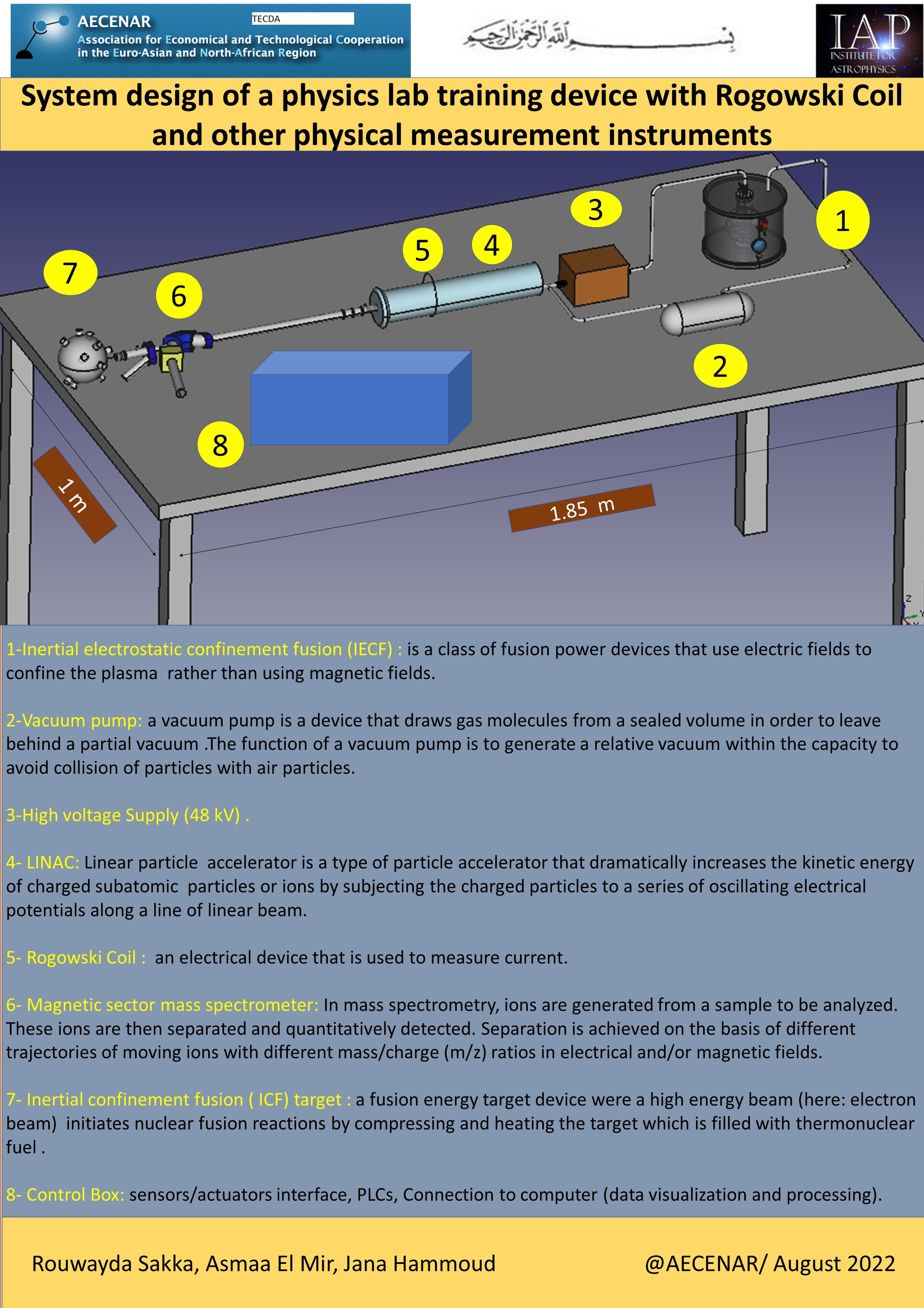
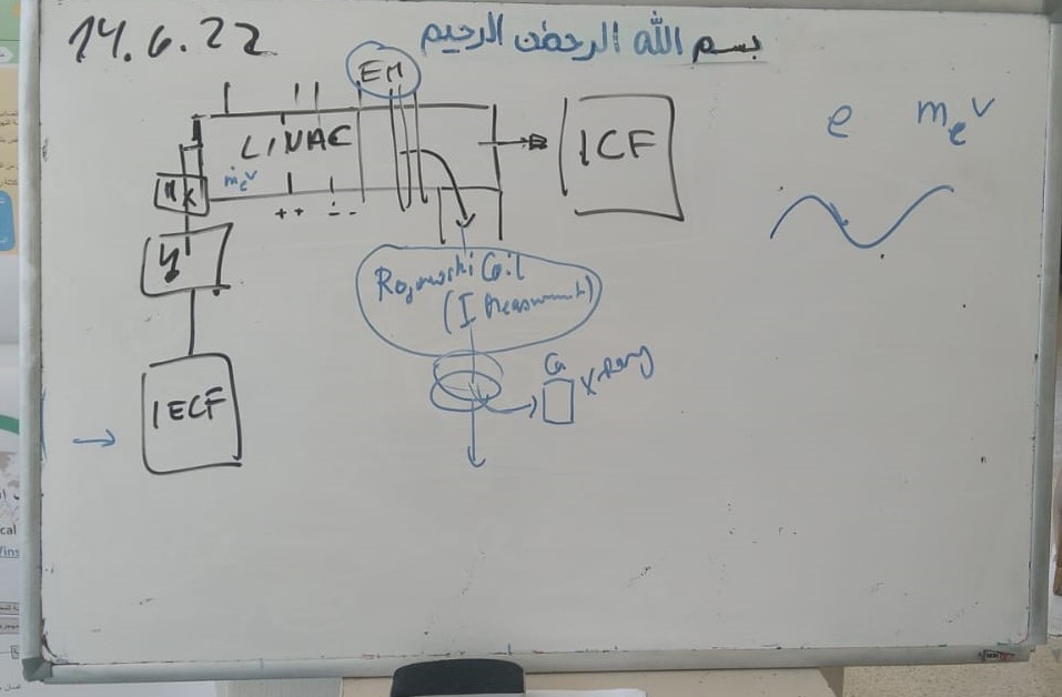
Our Physics Lab:


PhysicsLab testrig_systems Design (Poster) ( Last update:2.11.2022)
PhysicsLabTestrig_SystemsDesign(FCStd) (last update: 2.11.22)
Mass spectrometer and accelerator of electrons (FStd) ( Last update : 31.10.22)
System design (FStd) (Last update: 28.10.22)
Physics Lab (Basics, System Design of IAP-PhysicsLab) (Word) (Last update: 27.10.22)
 Mass Spectrometer Design (FStd file)
Old Design System (poster) (last update: 24.8.2022)


Pulsed Power Diode Accelerator / LINAC
Laser Based (Flue) Gas Detection
Physics Lab Process Control System (PCS)
Measurement Instruments
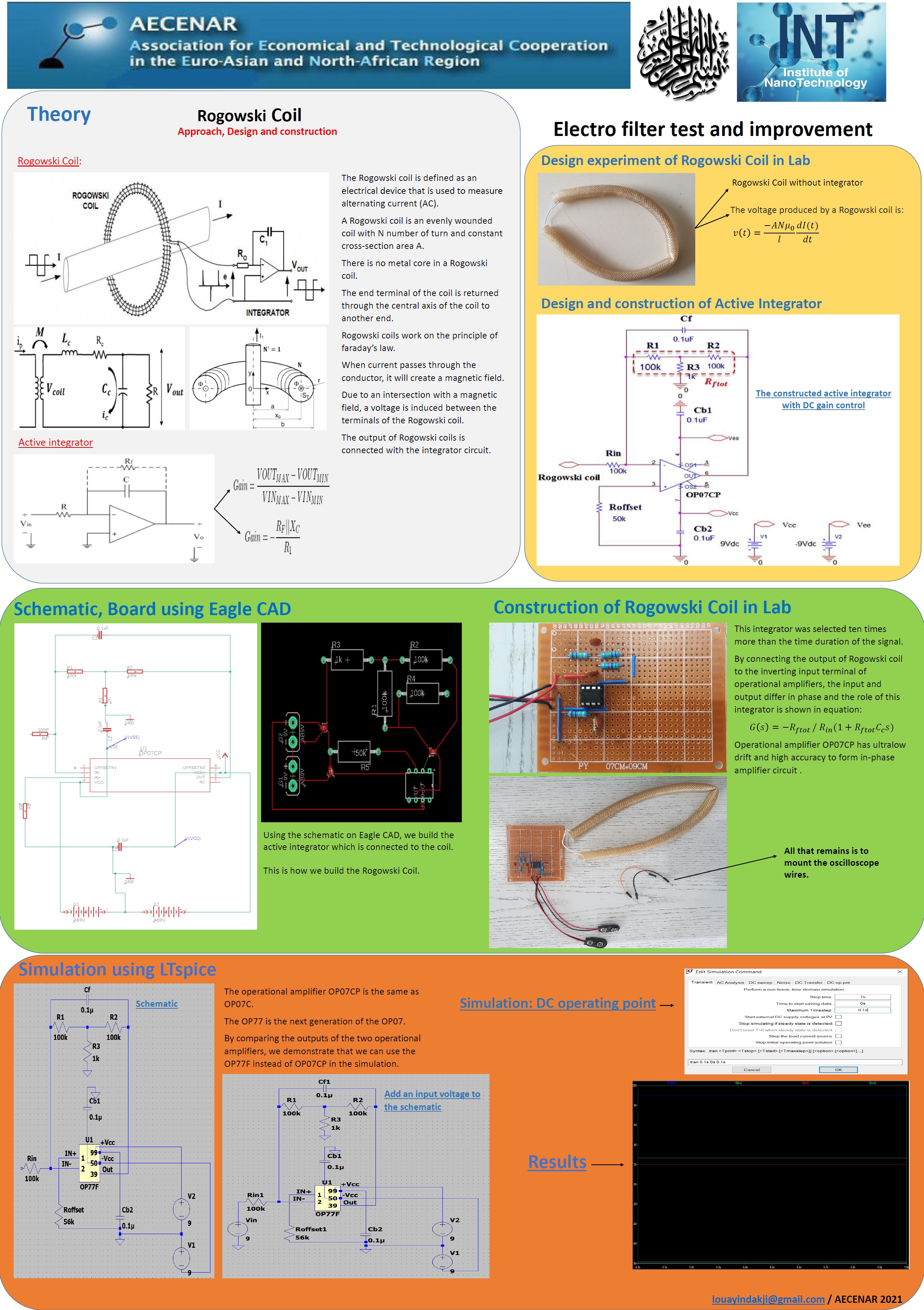
Electrofilter Measurement with Rogowski Coil (pdf)
Electrofilter Measurement with Rogowski Coil (docx)